Anatomy of a Center Fill
In the Front Row Experience, we explored the technique of using a small flown center fill to address the center coverage gap that commonly exists in Left/Right system designs - an area I have christened the Triangle of Sadness. In a sense, this fill is particularly interesting in that you hear it most when it’s not there - that triangle of undercoverage down in the pit is so common that once you get used to not having a gap there, it becomes all the more obvious when you do encounter one. In this article I’ll break down a few details about my approach to designing and aligning this fill to address some questions I’ve received about it.
Note that this is conceptually distinct from a larger center source such as is common in musical theater designs, which are used to reinforce a “center” or mono dialog signal across a large audience area. Here, we are focused on a center position that is not itself a main source, but rather a fill to cover the gaps between the main sources.
Mechanics
I have been implementing this fill with a small quantity of small-format line array cabinets - either three or four - suspended beneath the FOH lighting truss at the center position. (This is a hypothetical example, in which we assume spherical cows and cooperative lighting designers). In a lot of scenarios a point source with appropriate directivity could be effective as well, as long as it satisfies our dispersion and SPL requirements. I do find using a line array element gives a few advantages, particularly that it allows a bit of an asymmetrical coverage pattern: At the front of the coverage area (against the barricade), we want the fill to have a more abrupt coverage cutoff (a “sharper edge”) to reduce bleed onto the stage, whereas at the rear of the pit, we want the opposite - a more gentle roll-off to gracefully feather the transition into the coverage of the mains.
This means more overlap (smaller splays) at the bottom of the array, and less overlap (larger splays) at the top - the opposite of what we would typically expect from a line array. So in a sense, our array is “upside down.” Typically, starting with a frame downtilt of between 55° and 60° means the bottom cabinet impacts right on target along the barricade, but of course this depends on how far the FOH lighting truss is into the audience and its trim height. A pair of flybars (top and bottom) allows the center of gravity to land gracefully beneath the truss with no rolling. In sheds and amphitheaters, where the FOH truss can land over the stage apron, some angle adjustment may be necessary. This is easily facilitated by use of deck chain, slipping a few links in or out is usually enough to achieve the necessary change in inclination.
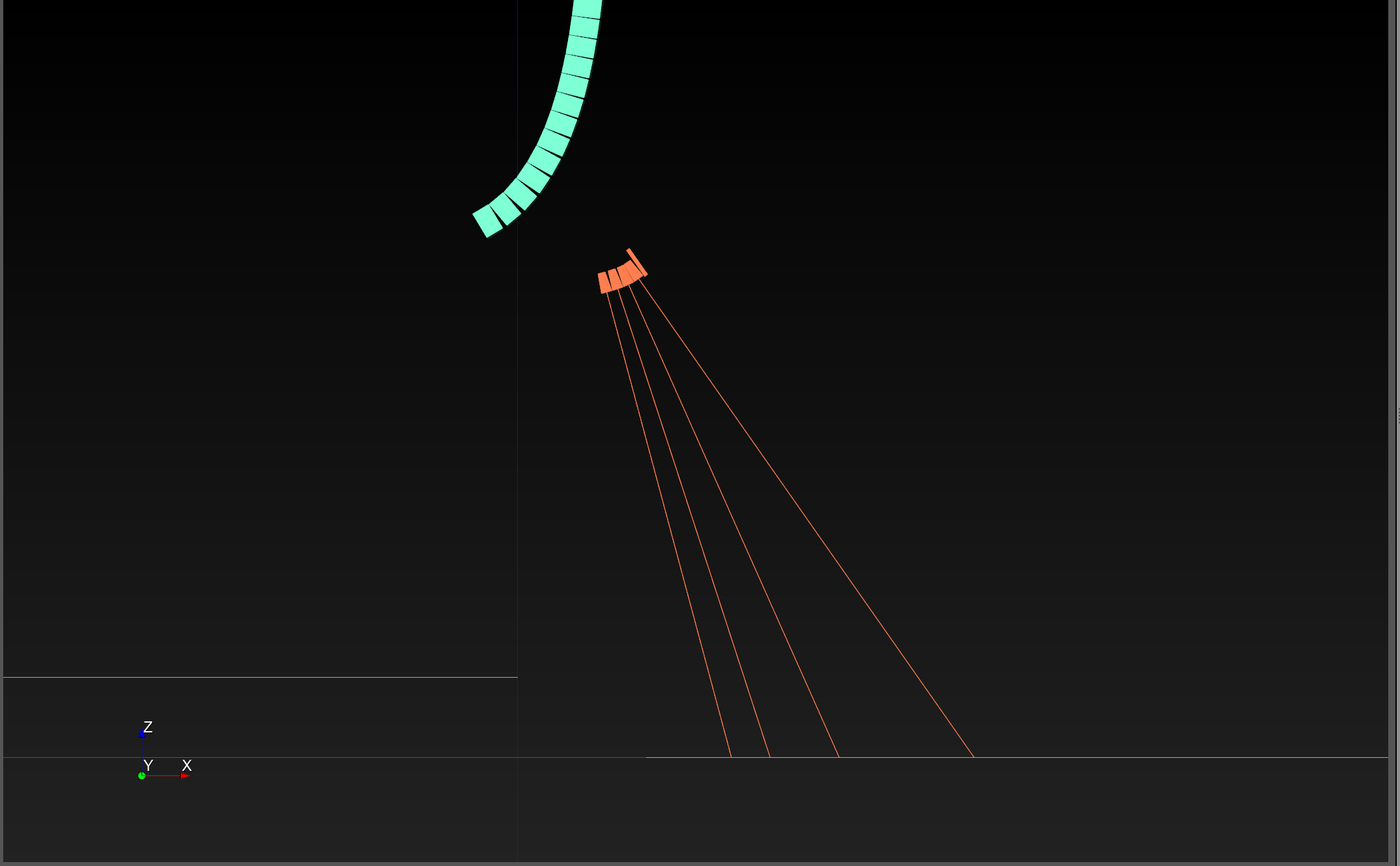
Figure 1: The “upside down” array splay strategy with the smallest splays at the bottom of the array
Equalization
Rising in the low-mid “power alley” between the much larger and more powerful main PA, this little fill doesn’t need to produce much, if any, low-mid energy, and in fact I prefer that it does not. Thinning out the low end of the response means less off-axis energy being dumped into the room which improves the situation for all listeners (and the artists). This is a prime example of Jim Yakabuski’s “360 Degree System Tuning” concept. You can test this for yourself by soloing the centerfill from mix position and sweeping a narrow filter until you find that range in the low-mid that really resonates - likely around 200 for elements this size - and then cut there. You might be concerned about the high frequency splash off the floor and back up into the space - that will clean up with humans in the room - the same reason our frontfills don’t penetrate into the venue as they do without an audience.
In truth, we don’t really need much energy below the range of the waveguide - the duty here is predominantly intelligibility. As such, I’m perfectly comfortable with aggressively stripping away low and low-mid content.
Conversely, we’re dealing with a smaller HF driver that might have extended response compared to the mains, so to ensure tonal consistency across the pit, we may need to tuck back a bit at the top end of the response as well.
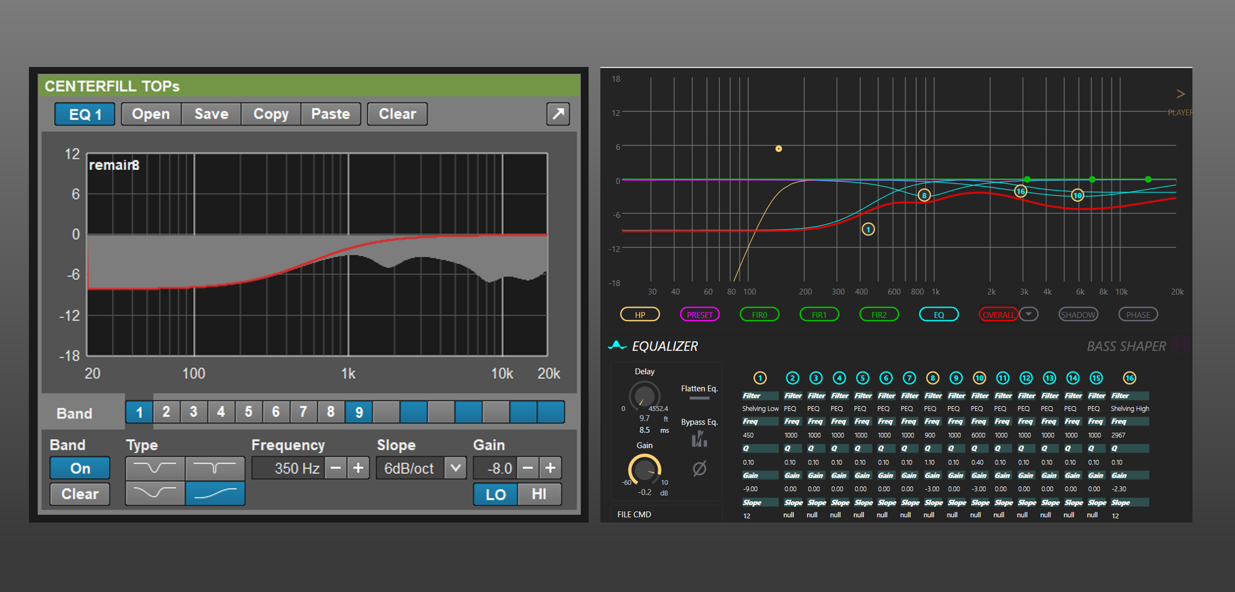
Figure 2 - Some example centerfill EQ responses. Note the similar trend. Left: 3x d&b audiotechnik Y8. Right: 4x RCF HL6
Timing and Alignment
We can eliminate the coverage gap by setting the level of the centerfill to match the level of the mains, creating level uniformity horizontally across the pit area (red line in Figure 3, below). Next, our timing point is at the seam halfway between the main and the fill, where they meet at equal level (the blue star in Figure 3). This is where they will be most interactive, and where our timing decision will have the largest effect on the resulting summation.
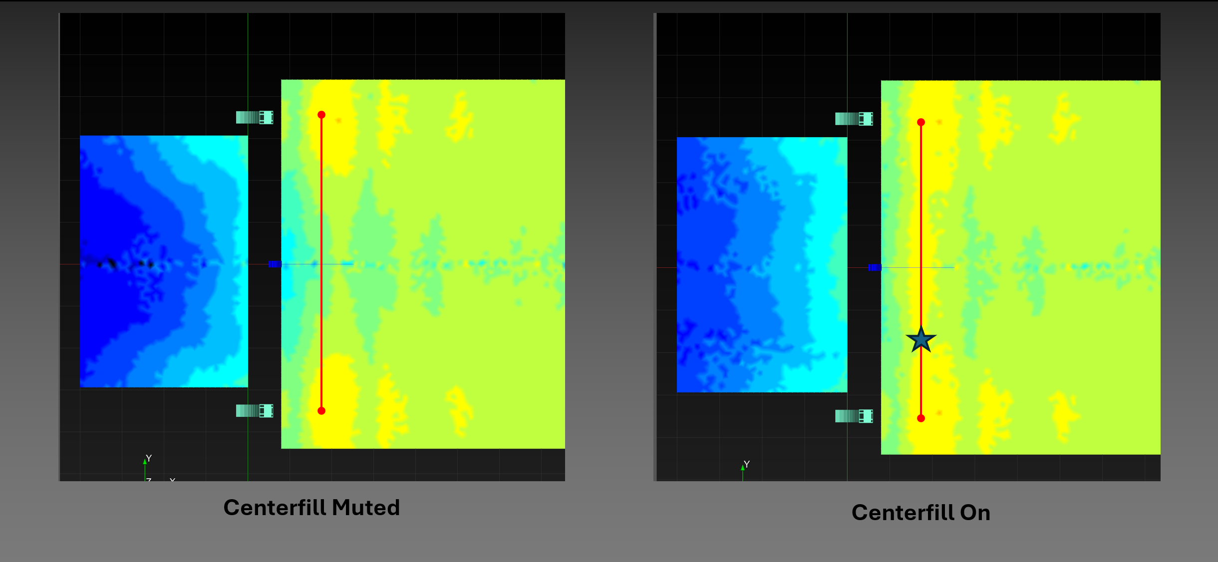
Figure 3 - Level uniformity across the front of the audience area
We want listeners along this seam to localize forwards towards the PA and stage, not upwards to the centerfill, so the fill should arrive a touch late. I typically find that about 2.5ms is the sweet spot to make the centerfill “disappear”.