Low Pass? Or No-Pass?
When it comes to tuning subwoofers, many mix engineers prefer to filter out energy at the top of the sub’s bandwidth more aggressively than the “stock” manufacturer tuning. Particularly on larger-format systems, in which the full-range mains have more substantial low-frequency extension, some mix engineers prefer the “cleaner” sound that results from more tightly band-limiting the subwoofers by adding their own LPF.
Not all subwoofers are created equal in this aspect - some models have a much more rapid roll-off at the top of their passband, while others roll off quite gently. From a system design aspect, higher frequencies being reproduced through the subwoofer array can lead to increasing beaming and generally undesirable polar performance. Some aspects of this are subjective - mix engineer preferences and goals vary, and different subwoofer models can behave quite differently above 75 Hz or so, both in terms of their polar pattern and the rate of roll-off in the frequency domain.
Most often I find that mix engineers tend to address this by adding a low-pass filter on the subwoofers, either on their console’s subwoofer matrix or in their front-end processing. We must keep in mind that a subwoofer already exhibits a band-limited response on its own, a combination of both the acoustic response and the filtering added by the manufacturer before we get our hands on it.
While this additional LPF will indeed effectively remove the excess energy at the top end of the sub range, this can create some undesirable consequences (and no, I’m not referring to messing with your main-sub alignment, an apparent fascination to which I do not intend to commit further attention; if you are worried about that, see Chapter 11 of my book Between the Lines, in which I make a case for why it may be more fruitful to focus on other concerns).
A brief mathematical tangent: we consider our sound systems’ behaviors both in the frequency domain (frequency response: magnitude and phase) and in the time domain (impulse response). Frequency response and impulse response are essentially two different views of the same underlying mathematical reality, and if we have one, we can calculate the other (that’s what the Fourier Transform does). No need to concern ourselves too deeply with this calculation - that’s what the software is for.
For the sake of this particular discussion, we need only focus on one specific property of this relationship between time domain and frequency domain: a compression of the signal in one domain results in an expansion in the other. (Figure 1)
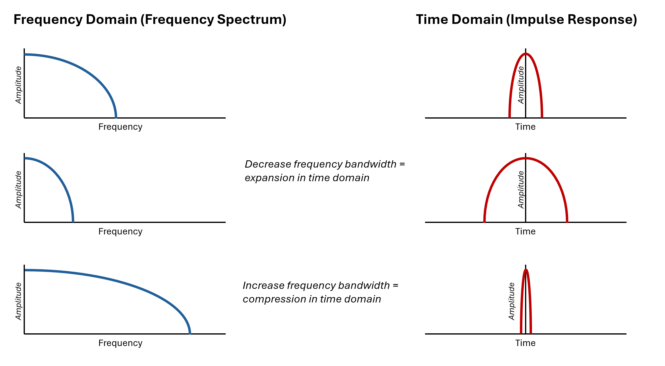
Figure 1 - increasing or decreasing the bandwidth of a system in the frequency domain (left) corresponds to a tightening or expansion of the system’s impulse response in the time domain (right)
Don’t worry, I’ll translate: more aggressively bandlimiting the subwoofers means more “smearing out” of the impulse response, which can lead to what might subjectively be described as a loss of articulation, “attack” or “punch.”
Note that this isn’t a side effect of a poor product design, or a ball being dropped by the manufacturer - this is a simple mathematical reality of systems with inputs and outputs.
We can achieve a similar “clean” sound but with less time-domain fallout if we can filter out excess energy at the top of the sub range without the bandlimiting effect of the low pass filter. In Figure 2, we see the response of a 4th order 90 Hz LPF in blue, and a 115 Hz parametric cut in green. Compare the impulse responses of these two filters (top pane): notice that the peak of the “hump” in the LPF response is almost 5 ms behind the IR peak for the PEQ, and the rounded-off leading edge of the envelope shape corresponding to the bandlimiting we saw in Figure 1. The sharp leading peak visible in the full-spectrum green response has been completely obliterated in the blue.
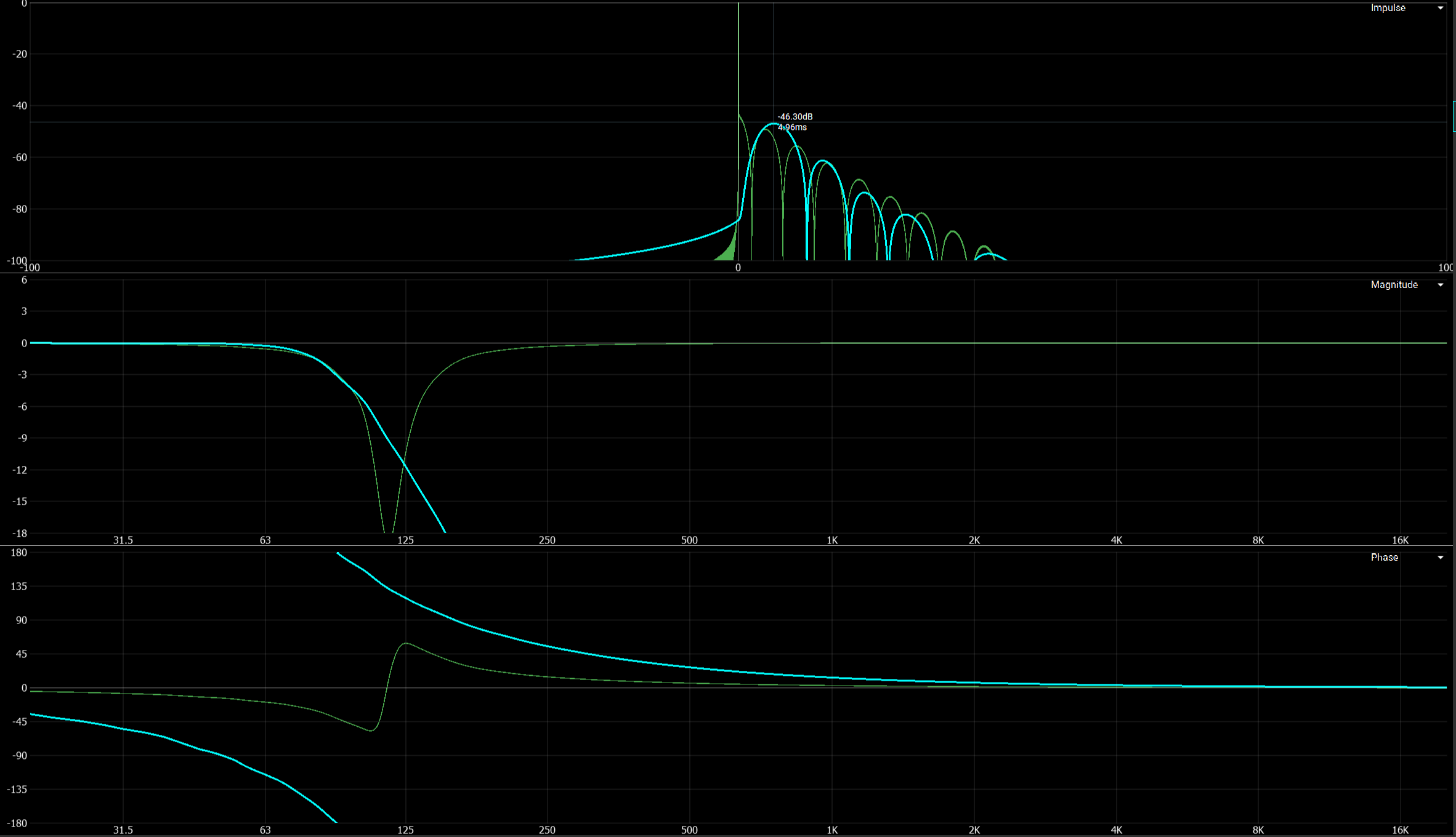
Figure 2 - comparing the IR, magnitude and phase of a 4th order LPF (blue) and a PEQ cut (green)
Although this discussion doesn’t focus on phase, it is illustrative to contrast the full phase wrap from the LPF against the smaller “out and back” phase response of the PEQ filter. The PEQ’s phase response remains closer to flat for much more of the bandwidth - this is the frequency-domain representation of more of the energy being kept together in time through the filter - i.e, less “time smearing.” (Measurement geeks are encouraged to examine the resulting group delay of these two filtering strategies for even more context.)
Okay, so it seems the mathematical tangent wasn’t so brief. More useful is what we can do with this insight - using a PEQ cut to filter out unwanted energy at the top of the subwoofer range affords a similar audible “cleanliness” while causing far less “smearing” fallout in the time domain. Practically speaking, I often end up “stacking” multiple PEQ filters in that range to achieve the desired sound quality - note (Figure 3) that their composite phase response still hangs within a third of a cycle, and maintains much of the corresponding time domain benefits versus the low-pass filter.
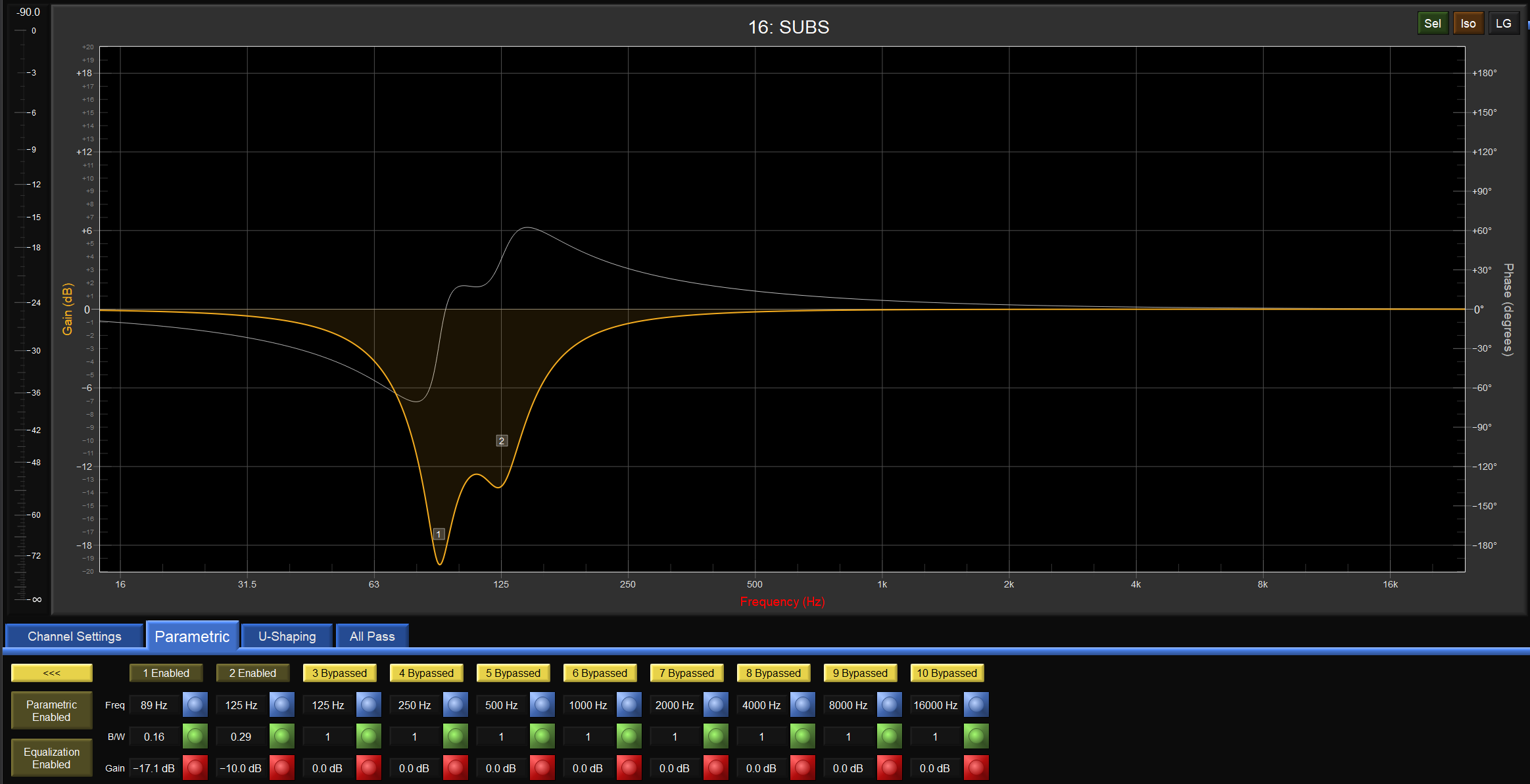
Figure 3 - stacked PEQ filters at the top of the sub range. The thin grey line represents the phase response
Generally speaking, I find the PEQ solution to feel perceptually “tighter” than a low-passed approach, and I find the PEQs easier to adjust “on the fly,” so I rarely add low-pass filters to my subwoofers these days. Your mileage may vary along with your preferences, and careful critical listening is recommended to compare the results of both approaches.
For those looking to dig deeper into the underlying concepts described above, I recommend The Scientist and Engineer’s Guide to Digital Signal Processing by Steven W. Smith, Ph.D., available for free at dspguide.com. In particular, the relationship between bandlimiting and impulse response can be studied in Section 4 of Chapter 10.